Time to have a go at the extruder, a little tricky since there is a good set of instructions for the wooden part of the LC extruder, but neither that or the Jr guide has any instructions for the gears, motor, hobbed bolt, the hot end itself etc. Luckily there’s nice instructions in the Printrbot Plus guide and also some in the Jr youtube video (part 5).
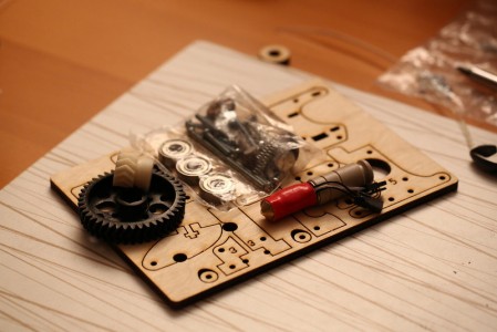
Extruder parts
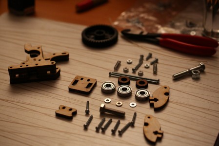
Extruder pieces laid out as in the step-by-step guide. Note the discrepancies…
Compare the picture above with the one in the guide and you’ll see that I have missing screws (again), perhaps they were intended to be included in the printer kit, I guess there might be different revisions with/without screws for both the extruder and the different printer kits. More on this later.
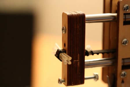
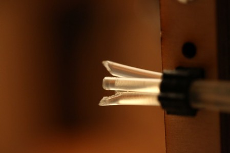
It wasn’t that difficult to keep the stack of pieces aligned before trying to put the screws in, then it got much trickier. I realized that instead of hex keys, toothpicks or other weird things I had the perfect material available! I simply snipped of few pieces of my 3mm filament! You need a pair of pliers to hold the small round washers of plywood at the ends still though, otherwise they’ll just rotate with the screws.
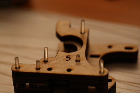
Extruder stack with filament pieces to help with alignment.
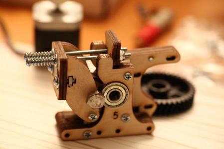
Assembled extruder.
After the assembly I realized that two screws I had left was either enough to secure the hot end on the extruder, or to mount the extruder to the printer. I used those two 1 inch 6-32 screws to mount the hot end. Luckily I had investigated metric equivalents to 6-32 and found that M3.5 was close. Unfortunately no store that’s close had smaller than M4 but I did buy some 25 mm M4s with both regular and nylock nuts the day before. These proved to work pretty well to mount the extruder! The head of the screws are bigger so no washers were necessary, the only problem was the nuts that were smaller so I had to use pliers to hold them in. They probably weren’t necessary though, the M4 did self-tap the hole and held on nicely even without the nuts.
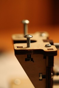
Testing using M4 screws to mount extruder.
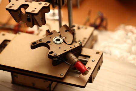
Added the hot end, about to mount the extruder.
After putting in the screws that keeps the hot end in I moved on the hobbed bolt with the big gear. Geting the bolt all the way through into the big gear took a significant amount of force but it seems good now. I put it in to verify that I had a reasonable amount of pressure against it and it might even be too much, will have to see how it works in practice. When I tested on a piece of filament, turning the big gear by hand, it was pulled through very nicely and had small indentations on it after it’s encounter with the hobbed bolt! I fastened the hobbed bolt with a nylock nut, I had both available since one of them came in the printer kit bag of screws and nuts, but the regular nut did not work very well even when just turning the gear by hand. It also seems like it might be a good idea to put a washer between the gear and the bearing, seems to be a bit of friction there right now.
My small white pulley gear was way too tight, almost impossible to get on the motor shaft so I used a small needle file to make the center hole slightly bigger. Which allows it to (as recommended) self-adjust when turned with the big gear. My gears look very rough, but they seem pretty OK. When turning them by hand it feels like there is an occasional stutter though but I’m hesitant to try to randomly file away bits and see if it helps, I’d rather try to print new ones if they are a problem (unless it proves to be really bad of course).
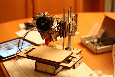
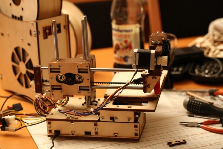
Extruder mounted, added stepper motor and the other bits and pieces.
Then I went back to some things I postponed earlier. The Z coupler was the first. When turning the rod by hand now that the Y/Z sandwich is mounted and the nut captured the wobble no longer seemed that bad. I want to see how it works like this first before I take any further action. Next up was the Z endstop, I pulled it out, added a top nut and then did a much better rough adjustment, too at least prevent the hot end from smashing into the bed.
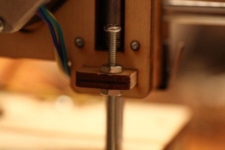
The Z endstop after adding a nut and adjustment.
I also took the single very long remaining 6-32 screw and a nylock nut and added them on the rear end of the Y assembly since I realized that without it being there and adjustable the extruder went well beyond the end of the bed before hitting the end stop switch. While fiddling with the end stops I had a look at the X one. Which of course had issues as well… I moved the longer 6-32 screw and its nylock nut on one of the ends of the X rods back to where I had it been originally so it hit the end stop. Not sure why I moved it before, I believe one of the pictures in the guide confused me and caused me to move it, I do remember being confused later on about having a nut sticking out where there was no reason for it and to check on it later. That’s probably why I left the screw hole by the end stop empty, then I obviously forgot about it. Tip: Have a notepad next to you while building to make note of things like this instead of relying on remembering it.
Finally it was time to do the first tests! I pulled off the lid of the base and pulled out the Z and X cables, hooked them and the rest of the cables up to the printrboard and powered it on. A green LED turned on which felt very promising. Connected the USB cable to my Macbook, launched Pronterface that I installed a few days ago and after selecting the right serial port it connected!
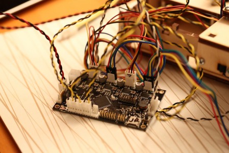
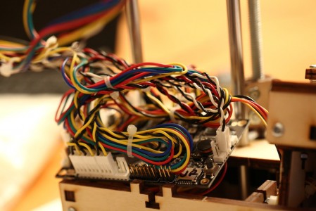
printrboard connected temporarily for testing, lots of cables.
Fun to play around with stepping back and forth on X, Y and Z to begin with. Once more the Z rod doesn’t seem that bad. Took forever for it go home but the end stop adjustment was pretty good, will fine-tune it when I’ve added tape to the bed and leveled it. The X one was also good but when I tried the Y home button things went bad. It moved in the wrong direction (which I hadn’t realized before) and pulled pretty hard on the belt when it got stuck. Not sure why; if it slipped, got stretched or any other reason but it’s definitely less tight now. Won’t tuch it until after an attempt to print though. I had seen people asking about motors going in the wrong direction on printrbottalk.com before so I simply did what I remembered others telling them and simply reversed the connector. Then it worked fine!
You can’t test the extruder with the hot end being cold so I chose to heat it up to 185 degrees. The hot end and termistor worked fine, and after it being heated up I extruded and reversed a few cm of filament (without any in the printer). Success overall! I did realize though that the extruder motor might have to be reversed also, it’s the same type of motor but I didn’t actually verify that the gears rotated in the right direction when “extruding” before.
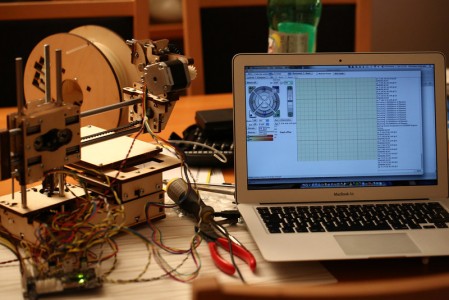
Testing with pronterface.
Pulled the cables out again and labeled all of the connectors, used a DVD marker for the white connectors and a silver colored pen for the black ones. Simply wrote X, Y, Z and E on the motor connectors, X S, Y S and Z S on the X/Y/Z endstops. And T E on the termistor for the extruder, Ext on the extruder heating wire
To get an idea on how much slack was needed on the cables I moved the extruder to the extreme Y and Z endpoints to check. Lots of zip ties later I had run out, will have to try to find my bag of small white ones to continue. So all that’s left before the first test print now is to add a few more zip ties and then try to shove the printrboard and cables into the base, with some guidance from the printrbot jr video #6. And perhaps reverse the extruder motor if needed.
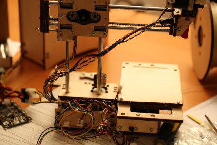
Result after a first round of cable management, actually might fit!
Update: Part 1 is available here and Part 2 here.


